LIZARD


At NUAV, Northeastern’s Drone Club, we leaders realized we needed to emphasize the fundamentals of drone design. So, we went from building a complex drone system with midflight exchanges (see the ADAPTS page) to building a basic research quadcopter that would be a platform for future drone projects. This drone became the Lightweight Indoor Small (Zmall) Autonomous Research Drone, also known as LIZARD. Eventually, I was the only person working on this project, and other leads contributed to other NUAV projects. So, I went through five quadcopter iterations, three of which I built, and developed a solid drone design. The first two iterations were only in CAD, but they gave me much-needed intuition about how to design complex drone assemblies. Then, I built the third iteration only out of wood and it did not fly. However, it taught me the physical limitations of drone frames and how important it is to check setup procedures. The fourth iteration was an exercise in designing for maintenance/usability, and the fifth iteration was the first carbon fiber drone I designed and was an amalgamation of all prior lessons.
Problem Statement & Goals
NUAV did not have a set of research drones that members could pick up, fly, and test code with within the span of a meeting. So, the club needed a standard drone design that was safe, easy to operate, could fly indoors, carry payloads that members would design, and run the code they would write.
This project was a way for me to build drone design principles from the ground up. So, the extent of my research included glancing at other hobbyist drone designs and using rough intuition to justify design starting points. In hindsight, this was admittedly a sloppy approach to engineering, but it resulted in A) a strong intuition of quadcopter design and B) fast iteration cycles. However, in between iterations, I ran thrust tests to validate whether the drone’s propeller-motor combination would generate enough thrust. Overall, the design was opinion-based besides a thrust test and improved by design intuition.
Goals
Be able to fly within a 10ft square drone cage
Be able to move to positions in 3D space autonomously
Be able to run computer vision algorithms
Carry small sensors such as cameras and LIDARs
Be safe to handle in an indoor environment
Non-Goals
Fast - This drone will be operating indoors with limited space, so there is no room for speed
LIZARD V1

At first, I decided to just start with whatever simple drone shape I could come up with, which resulted in the CAD version of LIZARD V1 (shown right). Meanwhile, Jackson, an engineer at NUAV, created a model for the front camera mount, which would hold an Intel RealSense.
The design was extremely barebones and did not hit many structural goals. Since I made the arms 3mm thick carbon fiber plates, they likely would have snapped if the drone ever fell. This would have been a waste of time, resources, and club budget. Additionally drone’s body was just two plates connected with four standoffs. This meant that if the drone fell on its front or back, there wouldn’t be enough standoffs to resist the impact, and the entire top plate would shear forward. I also realized the body was far too big to be convenient for storage and handling and wasn’t feasible for small indoor drone cages. So, it was time to start another model with LIZARD V2.
LIZARD V2

I addressed LIZARD V1’s issues by changing the design of the arms and the body and by adding holes to the frame for aesthetics and function. Starting with the drone’s body, I used thicker 4mm plates and added ten standoffs instead of four from the prior version. This would give the drone’s body plenty of resistance to bending moments and shear forces coming from all directions. I also reduced frame weight by cutting materials that were 3mm offset from the frame’s perimeter and bolt connections. This is why there are polygonal gaps around the body. In those gaps, I added parallel sections that were 10mm wide to add some structural support.
Despite colleagues warning that plated arms would crack on impact, I committed to the flat arm design. I wanted to see how these arms faired physically. Maybe these warnings were wrong, and thick arms are possible? After all, all 5”-class racing drones use 6mm+ thick plated arms. If they did break, I wanted the arms to be easily replaceable, so inspired by the Martian II FPV drone frame I used for my first-ever drone, I designed a bottom plate that would screw into the arms and into press-fit inserts in the drone’s body. This would keep all arms fixed relative to the frame and make the design simple. One downside with this design-meta was that if one arm broke, I would need to disconnect all arms from the body.
By the time I finished this drone design, I had realized there might not be enough room for potential payloads, and some critical components would end up getting shoved and zip-tied into whatever cracks were available in the drone. Also after a few months of only CAD models, it was time for me to build a version, so LIZARD V3 would become the largest and first physical version.
LIZARD V3

Admittedly frustrated with iterating exclusively through CAD and not learning how to physically build a drone from scratch, I decided to create a design with excessive room, using the arms I designed in V2. The result was a large rectangular-like body with 12 standoffs linking two plates together. At the bottom, I designed a plate that clamps the four arms to the drone’s body.
I added several design features to make the drone functional. I drew the propeller’s diameters to adjust the length of the arms. I added some electronics like the power distribution board, Jetson Nano companion computer, and Pixhawk flight controller (the mount for which I designed). I made sure there was a 3mm offset from the bolt holes in the frame when I made cutouts. I also added slots on the top of the plate for battery straps and for routing the battery’s power connection into the body of the drone.
After I finished the drone’s design, I built the frame, mounted the electronics, and attempted a first flight. Since this was its first build, I decided to laser-cut the frame out of cheap, 1/8-inch thick wooden sheets. This way, if a piece breaks or something isn’t fitting right, it would be easy to cut a replacement. Overall, I spent two nights in the AerospaceNU lab building and troubleshooting this drone.
The first harsh lesson I learned was that my beloved plated arms were too flimsy. Although they were made of wood, which isn’t as stiff as desirable carbon fiber, the amount I was able to bend them by hand was analogous to how much they could bend if the drone fell midflight and impacted the arm. I could bend these arms up and down by a couple of centimeters. Also, if I shook the drone up and down by the frame, the arms would wobble. If I wanted to commit to the plate design, I could specify thicker arms, but this would make the drone more expensive while our club had plenty of 12mm diameter carbon fiber tubes in stock. There was no denying that plated arms, although they would be feasible with extremely thick plates, weren’t viable for the next LIZARD version.
The second lesson was the subtle impact wires have on how you can organize your electronics. When I placed these electronics, I thought I could bend the wires wherever I needed, and the drone would be organized. But when I actually built the drone, I suddenly realized how restrictive each wire’s bending radius was. Plus, I scrapped together ESCs from old NUAV drones to control the motors, but these ESCs already had long, thick connectors on them. So, because of poor planning I had to cram, zip-tie, and loop wires and electronics in and around the frame. In the next version I would have to clearly plan which electronics I want to use, what kind of connectors they would have, and add spacing to account for unexpected wires.

Regardless of these two major issues, I connected the drone to my remote controller and attempted to hover, but something unexpected happened. I took time before the test to make sure my motors were spinning and were spinning in the correct directions. I did this by plugging in a LiPo battery and slowly ramping up the motors (without propellers, of course) through the QGroundControl software. But when it came to hovering, the drone couldn’t even get off the ground. It wobbled and veered to the left.
I was stumped. I thought about the problem and I reasoned that since the arms were so flexible, the moments it generated messed with the drone’s pre-build PID control. In other words, as a motor spun up, the arm would deflect, which redirected the thrust and triggered the flight controller to reverse compensate for the discrepancy. But as it tried to correct, the motor would either thrust up or thrust down and bend the arm again,n triggering another discrepancy. This would repeat and cause a wobble in the drone’s frame.
However, this was not the issue. Because of my rushed approach to building this drone, I neglected to correctly specify the order of the motors. So when the drone wanted to spin motor 1, which it thought was the upper left motor, it would actually spin a different one, which ruined the benefits of the closed-loop control.
Overall, this version housed the necessary components and demonstrated that the drone could produce lift, but the poor quality of flight, lack of structural stability, and bad electronics placement showed me I had to continue with a new iteration. In this new iteration, I switched to tubular arms and used an abundance of frame layers to place my electronics.

Measuring Motor-Propeller Thrust
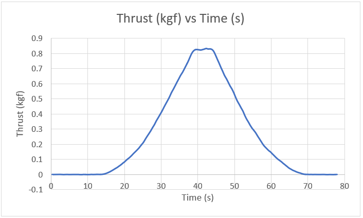
After building a physical version, I realized I needed to ensure the chosen combination of motors and propellers would generate enough thrust. From a fellow NUAV lead’s recommendation, I chose a 2806.5 motor with 1800 kV. This XING motor was highly efficient compared to other similarly sized motors. He recommended the 2806.5 size because it generates enough torque to spin 7-inch diameter propellers with a sufficient amount of thrust, and he chose the 1800kV efficiency due to its higher efficiency compared to other available motors. Despite this chosen combination, I wanted to verify how much thrust the motor would produce at 50% throttle.
I used a TytoRobotics Series 1520 Thrust Stand to get a plot of thrust vs ESC signal and thrust over time. I learned that at an ESC signal of 1400 microseconds, the motor would generate about 0.82kg of thrust. Across four motors, this meant that the LIZARD quadcopter could generate 3.28 kg of lift. This would be enough for a 2-kilogram payload, and for LIZARD V4, this meant a thrust-to-weight ratio of about 4.

LIZARD V4

Using the lessons from LIZARD V3, I designed LIZARD V4 to have stronger arms and a dense electronics layout. Firstly, I no longer committed to the flat arm design and instead used carbon fiber tubes that were 12mm in diameter. Secondly, I used multiple stacks of carbon fiber plates to organize my electronics.
I designed the arms to interface with a standard clamp design a former lead of NUAV designed during the ADAPTS project. These clamps were 3D printable and had embedded heat-set inserts, which allowed them to easily mount to any plate design and maintain a clamping force on the tube. So, I designed LIZARD V4 such that you could slip carbon fiber tubes through the clamps and secure them wherever needed. This meant at one end of the tubes, I could design a plate to hold the motors, and at the other end, I could design two contact points for holding the arm.
I made the frame such that there was one central body that plates could stack on top of. This central body had two large frame pieces that were supported with standoffs and mounted the flight controller and clamps for the arms. On top of the main body, I mounted the telemetry radio and power distribution board, as well as an add-on plate that supported the battery. On the bottom of the main body, I mounted a Jetson Nano, which would be the drone’s companion computer, and protected it with another plate, which the drone stood on when it wasn’t flying. This layered design was great for keeping the drone in a small area, but it made assembly and maintenance dreadful.
I built the drone out of wood to assess its functionality and realized the downsides of the layered design. I made this design using 1/8in thick wooden plates and 12mm diameter wooden dowel rods. I was able to build the central frame easily, but when I wanted to add electronics to the top and bottom, I realized I neglected wire management. I soon found myself cramming excess wires in any available gaps in the frame and zip-tying electronics in strange positions. Eventually, I had a compact drone design, but it was too compact and became a pain to fix when issues arose.


Within the drone, I mounted and set up the electronics. I chose a Pixhawk 4 flight controller, an XM+ receiver, an M9N GPS, a 4S LiPo battery, and some spare ESCs NUAV had in inventory. I uploaded PX4 open-source firmware and configured the drone’s settings in QGroundControl. I connected it to my personal Taranis QX7 and attempted brief hover tests in the lab. As a result, the drone spun around out of control, as shown in the video to the left. Although this was entertaining to watch, there was something wrong with the way I had set up the motors. I eventually realized I had wired the motor’s ESCs into the flight controller in the wrong order. After swapping to the correct order I was able to achieve stable flight! In hindsight, this was the issue that caused LIZARD V3 to shake. Regardless, I had a wooden drone that could fly and access GPS data! Now, it was a matter of flying it outdoors.
LIZARD V4 Outdoor Test
In LIZARD’s first outdoor test, it successfully traveled to GPS waypoints all on its own. I, alongside members of NUAV, traveled to Northeastern University’s Dedham Campus, where we had permission to fly. We specified a flight path through QGroundControl, and after plugging its battery and manually hovering it a safe distance away, we launched it from one of our laptops. The drone rose a few feet from the air and traced the path we specified. It then performed a Return to Land (RTL) maneuver where it rose several dozen feet in the air and then slowly landed on the grass.
We made one more flight test afterward, and this was when LIZARD V4 met its end. During manual flight, one of our members was gently controlling it until it suddenly shot toward the east. GPS was not enabled, nor was any autonomous mode switched. It was almost as if something possessed the drone to fly towards the gravel nearby. The moment the pilot lost control, he disarmed the drone, and it crashed into the gravel, splitting the wooden arms and filling the motors with dirt. LIZARD V4 was dead, but the lessons it provided were invaluable. It was time to move on to LIZARD V5, the final LIZARD iteration.


LIZARD V5
The final iteration of LIZARD was a combination of all the lessons I learned from each iteration. To recap, from V1 and V2, I learned that drones need small, rigid bodies that are large enough to comfortably store all the electronics. From V3, I learned that flat arms are far too weak and that one plate for the electronics was too big. Finally, from V4, I learned that having electronics stacked on multiple layers made maintenance, assembly, and wiring tedious. So, I designed LIZARD V5 with all electronics mounted on the bottom, its companion computer centered in the body, its battery and GPS mounted on top, and arms short enough to have a compact profile while producing lift. This way, the body of the drone uses no more than two plates, and the only wires that route between plates include the GPS cable, battery cable, and the Jetson’s USB and power cables.

For this iteration, I designed two unique clamps that minimize the drone’s profile and make disassembly easy.
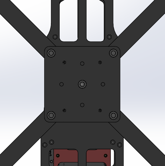
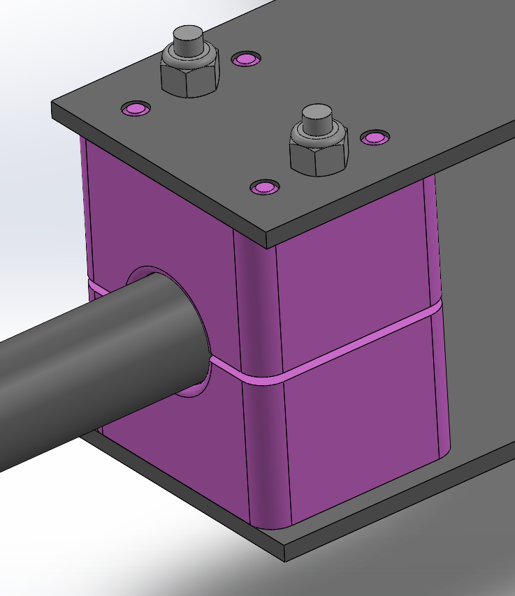
The first clamp I designed held the arms within the body of the drone. Many drones have two arm clamps to guarantee the arms are secure from bending forces, but they take up too much space. So, I designed a single thick clamp to hold the arm. I checked whether it would actually sustain an impact force by doing a bolt analysis on the 3mm bolts on either side of the arm and by doing a bending force study as if the arm were a cantilever beam. Under both analyses, the design would hold up against an impact force with a sufficient factor of safety. Additionally, I designed the mount with heat set inserts on the inside and nyloc nuts on top. The heat set inserts provided a strong local clamping force that gripped the clamp to the arm, while the nyloc nuts held the plates to the clamp.
The second clamp I designed was for mounting the motor to the arm. I designed it such that there was enough area for clamping and such that someone could unscrew the motor using a ball-head Allen wrench. I also included heat set inserts on the inside and nyloc nuts on top. Below is a video of me attempting to twist the arm out of place and a photo of the motor mount.

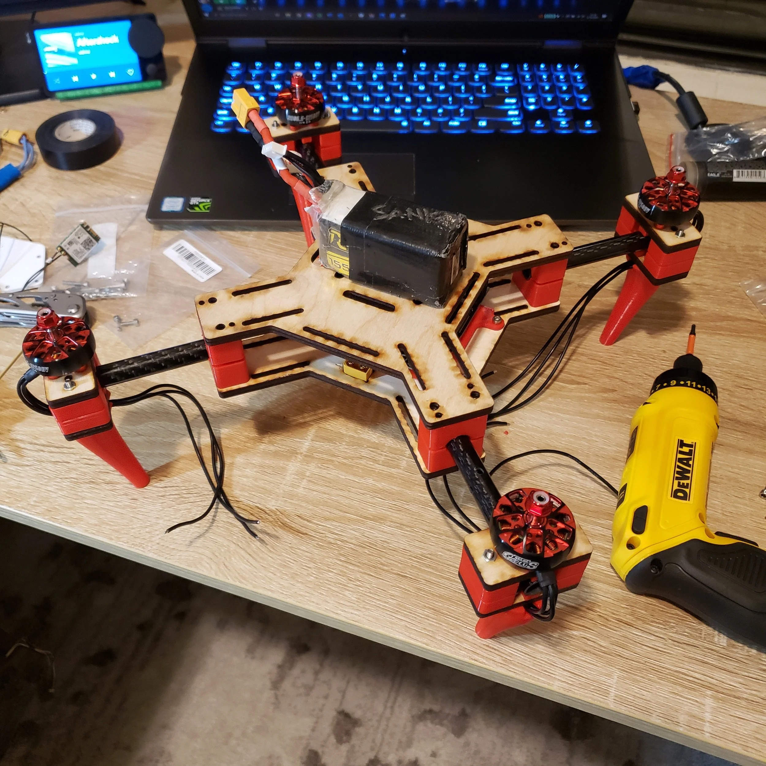
I manufactured the drone using carbon fiber plates and 3D-printed parts. I used my personal 3D printer to print the clamps, feet, and GPS mount out of red PETG plastic. Afterward, I cut 12mm diameter carbon fiber tubes in a vent hood with a hacksaw and with plenty of water dripping on the material to minimize airborne carbon shards. I also laser-cut a mock version of the drone frame to check whether everything would fit. After verifying that the design was functional and assemble-able, I sent .DXF files to CNCMadness to cut the 3mm carbon fiber plates for cheap.
Once the plates arrived, I began assembling them using M3 hardware and lots of VHB tape. I taped the flight controller, power distribution board, telemetry radio, receiver, and four individual electronic speed controllers to the bottom of the drone. Meanwhile, I used a preexisting mount for the Jetson nano and screwed it in the center of the drone. I also press-fit an XT-60 female connector into the drone’s frame so that when people plug and unplug the battery, they have a common mounting point. This made routing and protecting the battery wires much easier.