Tarsier

A render of the Frog research drone with Tarsier V5 mounted on its front.
I developed a front-facing camera gimbal mount called Tarsier for Northeastern’s Drone Club, NUAV, to enhance video stability during drone flights. I designed, with the help of a mentor, an actively stabilized gimbal to counteract the drone's rotational movement. Goals included controlling the camera’s rotation within +/- 180 degrees, isolating vibrations, ensuring smooth motor rotation, and maintaining a compact profile. Through three iterations, I tackled challenges such as small-form factor designs, designing for machinability, and justifying designs through calculations. Through these, I learned rigorous design processes, the importance of using data to justify design, and how to think outside the box to meet product functional goals.
Problem Statement & Goals
Northeastern’s Drone Club, NUAV, had a fleet of research drones called Frogs that needed gimbaled front-facing cameras for stable video during flights. When a drone moves forward, its entire body rotates, which causes any fixed cameras to rotate with it and sadly look at the ground. With active stabilization, a front-facing camera can pitch up while the drone pitches down, meaning the drone is always looking forward. This feature would enable the drone to continue to perform more kinds of vision-based missions.
Non-goals
Stabilization in the roll or yaw axes
Use of materials other than 3D printed plastic, carbon fiber plates, or small metric hardware
Goals
Have active stabilization from +/- 180 degrees along pitch axis
Isolate high-frequency (100-200 Hz) vibrations from the drone propellers
Have smooth motor rotation that doesn’t induce video shake. This involved:
Precise motor control
Continuous positioning options
No backlash in the gearing system
Fit the entire assembly within a small profile:
Within the drone’s body (i.e. doesn’t stick out of the existing profile)
Allows the drone to still slip through the multidrop assembly (an assembly that stacked drones for another NUAV project)

Diagram showing the forward pitch angle of a drone (phi). (Source: https://towardsdatascience.com/demystifying-drone-dynamics-ee98b1ba882f)

Screenshot of the Frog’s CAD model with the working area of the Tarsier assembly shown in the red volumes.
Before I took on the project, work was done by a prior member of NUAV on two Tarsier iterations. They designed the gimbal so that there was a servo directly mounted to the camera. Although a simple design, it had a lot of backlash since the servo had loose fit gears inside and low positional resolution.

Prior Research
After looking at prior Tarsier versions, I thought that using cables to drive the gimbal could be an effective solution. So, I looked at elbow joint designs by Skyentific, an engineer on YouTube, who made a cable-driven, 3D-printable elbow with a reduction. I also looked through KoreaTech’s LIMS2 robot arm, which also used multiple cable-driven reductions for their elbows.
From these sources, I brainstormed some early cable reduction concepts. I explored how different placements of the driver pulley, idler pulleys, and driven pulleys allow motion in confined spaces.


Tarsier V3

The initial design started from two prior versions of the camera mount. So, this design was called Tarsier V3 and was a revamp of several old concepts, including 3D printed size mounts and a 3D printed camera mount. The intent was for the cylinder jutting out to the right of the above image to have two small holes for cables to route through. The cables I chose were cheap 1/16 in. cables off Amazon. I chose these cables because they appeared to mimic the same properties of the elbow joints that inspired me to go with this cabled design. Sure enough, my lack of thorough analysis for choosing the cable lead to this design’s failure.
There were many pitfalls with this design, including a 3D print and a mounting configuration that wouldn’t fit inside the drone. Furthermore, after 3D printing the assembly, it became apparent that cable tensioning (which is a prerequisite for eliminating backlash) would be impossible with the materials and space available. Additionally, the steel cables likely would have transmitted motor vibrations into the camera video feed.
Tarsier V3 Assembly
What Functional Goals Did I Achieve?
The design’s side brackets were stiff and constrained the camera to rotate in only the pitch axis.
Theoretically, it would have allowed continuous motion due to smooth bearing with large inner diameters.
The brackets were vibrationally isolated from the frame with three silicone rubber balls on each side.
What Needed Fixing?
Steel cables were inherently an undesirable design meta due to their transmitting vibrations, being difficult to tension, having a large bending radius, and being too large for a feasibly small camera mount.
The 3D printed side plates, although functional had long manufacturing times.
Tarsier V4
The next attempted design meta was to use 3mm thick 158-2GT rubber fiberglass timing belts. These timing belts had compliance that reduced backlash and isolated some vibrations from the motor to the camera. The belts, alongside M2 hardware, drove 3D-printed part designs that were manufacturable. Another addition to this version was the successful design of a bevel gear assembly that was separate from the rotating camera assembly.
NUAV already had the motor in stock, which was designed to work with commercial motorized camera gimbals. Since the vertical space within the drone was too small to fit the motor vertically, I used existing parameterized models of bevel gears to transmit the rotation of the motor to be in line with the camera.
Across from the motor assembly was a set of parts that transmitted rotational motion into the camera. I designed a belt tensioner that shifted an idler vertically, stretching the belt. I mounted this idler to two carbon fiber plates that press-fitted into the base of the assembly, which held a 3D-printed part with a wide ID bearing. The camera mount itself had heat set inserts inside. This led me to design a gear to mesh with the belt that screwed into the camera mount. I included semi-circular extrusions in the camera mount and the gear to design for hard-contact rotation.

What Functional Goals Did I Achieve?
Has active stabilization along the pitch axis due to the incorporation of the belt and bevel gear system.
Theoretically isolated high frequency (100-200 Hz) vibrations from the drone propellers due to rubber balls holding the camera mount, threaded rubber standoffs holding up the gimbal motor, and the belt isolating the gimbal motor from the camera mount.
Continuous positioning options due to the fidelity of the BLDC gimbal motor
No backlash in the gearing system due to compliance in the belt.
Fit the entire assembly within a small profile:
Within the drone’s body (i.e. doesn’t stick out of the existing profile), which drove the desire for a bevel gear assembly.
Allows the drone to still slip through the multidrop assembly which is inherently true due to the above bullet.
What Needed Fixing?
An oversight on my part was that when the top plate of the drone was mounted, it would interfere with the camera mount, and it could not rotate +/- 180 deg.
Precise positional control was a challenge since the motor was a BLDC motor
An oversight on my part was that since the camera was mounted on rubber balls and a belt was in tension with a hard-mounted motor, the entire camera assembly was skewed to the left. This was unacceptable for the end goal of computer vision, so there needed to be another version.
Tarsier V5

Tarsier V5 Assembly Without its Cover

Tarsier V5 Assembly With its Cover
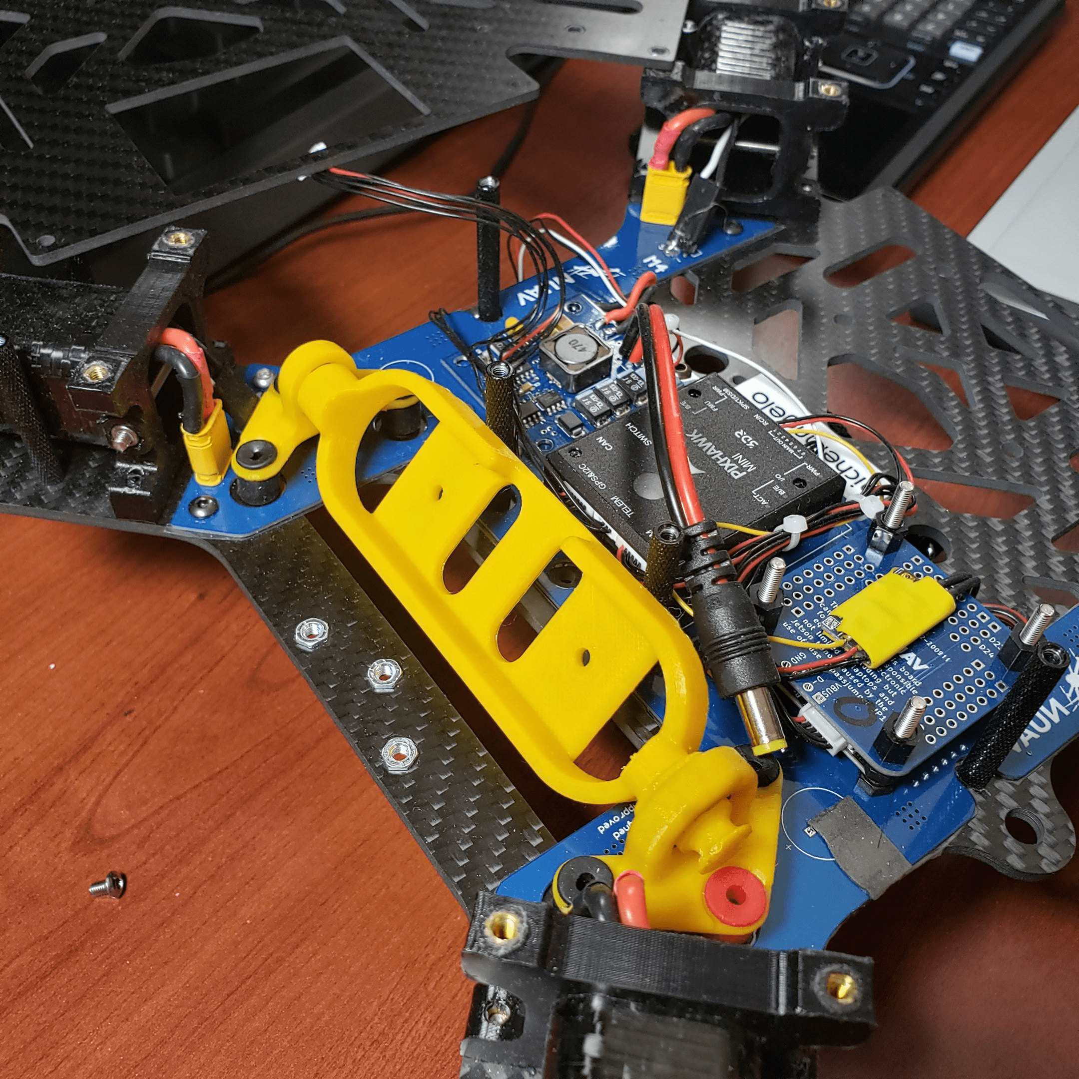
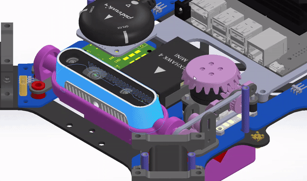
The final version, Tarsier V5, took the camera outside of the frame. After reviewing multiple designs, we learned that trying to condense the assembly inside the small drone volume was an unnecessary requirement. Furthermore, the belt configuration was inherently a complex design that required multiple moving parts, which increased manufacturing time, increased assembly time, and increased probability of failure. So, TarsierV5 stuck out the front of the drone and had the gimbal motor directly mounted to the camera’s axle. Opposite the motor was a press-fit bearing connected to an axle I designed and had machined. The assembly used 2mm thick carbon fiber plates to add structural integrity and a 3D printed cover for aesthetic purposes and to protect the mount in case of a crash.
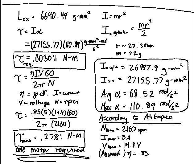
One question that came up while designing this version was whether we needed one or two motors. One motor would be cheaper, but it may not have had enough torque to synchronize the camera with the changing pitch of the drone. Two motors would guarantee the camera is in lock with the drone’s pitch, but it would require more power, more cables to manage, and be more expensive. So, per my mentor’s suggestion, I did the calculations to decide. I referenced the RealSense camera’s mass from its technical sheet and modeled the weight of the frame in SolidWorks. That way, SolidWorks was able to give me the rotational inertia of the gimbal assembly. Then, I found the equation for modeling the torque of a brushless DC motor and found that torque is directly proportional to current and voltage but inversely proportional to speed. I added an efficiency factor, assuming the motor would produce 85% of the ideal torque. Finally, I used data logs from a recent flyout to justify the maximum acceleration the motor needed to induce. This data came from two members who flew a duplicate of the drone outdoors. I retrieved the gyroscope’s measurements along the pitch axis and found a maximum acceleration of about 110 rad/s^2. Now I had all the pieces to determine whether I needed one or two motors. I calculated the required torque was 0.003 N-m, while the torque one motor could produce was 0.28 N-m. This meant that one motor would be able to spin the gimbal easily.
My First Technical Drawing!

My first technical drawing of the axle for the Tarsier V5 assembly.
The axle that was opposite the motor was my first attempt at creating a technical drawing. It used press-fit tolerances based on a guide from the Misumi Corporation. It also used a cross-sectional view to specify the depth of four tapped M2 holes. Although I wouldn’t consider this drawing high-standard, I learned a lot about what machinists need to know when receiving a drawing. This drawing also kickstarted my understanding of applying reasonable tolerances for a part.
Afterward, I used a laser cutter to cut wooden sheets and created a mock version of TarsierV5 to spot any functional issues with the design. When I assembled it, the housing was able to rotate smoothly. Furthermore, the axle met my specified tolerances and successfully press-fit into the bearing.
Troubleshooting Carbon Plate Cutting

I then asked members of the capstone lab at Northeastern to use their waterjet to cut carbon fiber plates. However, one part went missing, and the water jet was decommissioned soon after. So, I used the desktop water jet in the AerospaceNU lab to attempt to cut the remaining part. But this machine was unreliable, and carbon fiber parts were blowing out. So, I used a design of experiments to test different cut settings. I successfully cut the part but the part did not meet the specifications.
Eventually, the club shifted its focus away from the Frogs and toward the ADAPTS Research Project. Ever since then, Tarsier has been postponed until we need a gimbaled camera again. Regardless, I learned a lot about rigorous design processes by iterating through several versions of the camera mount and specifying precise dimensions at such a small scale.

Results
I was able to get carbon fiber plates for the camera gimbal, but the waterjet was decommissioned soon after. So, I used the desktop water jet in the AerospaceNU lab to attempt to cut the remaining part. But this machine was unreliable, and carbon fiber parts were blowing out. So, I used a design of experiments to test different cut settings. I successfully cut the part but the part did not meet the specifications.
Eventually, the club shifted its focus away from the Frogs and toward the ADAPTS Research Project. Ever since then, Tarsier has been postponed until we need a gimbaled camera again. Regardless, I learned a lot about rigorous design processes by iterating through several versions of the camera mount and specifying precise dimensions at such a small scale.
What went well
Have active stabilization from +/- 180 degrees along the pitch axis due to a separate, unconstrained pitch axis
Isolate high frequency (100-200 Hz) vibrations from the drone propellers due to rubber dampening balls
Have smooth motor rotation that doesn’t induce shaking in the video. This includes:
Continuous positioning options, due to direct connection to the motor
No backlash in the gearing system because you can’t have backlash in gears if you don’t have gears
Fit the entire assembly within a small profile:
Allows the drone to still slip through the multidrop assembly, which was accounted for in the design
What needed improvement
A precise motor control loop with a control board
Several carbon fiber parts not being reliable enough for completion
The USB-C connector, in this case, was not shielded enough, which meant the design that relied on a small 90-deg USB connection was unfeasible.
Ideas for what to do differently
Communicate independently with the electrical team on the control aspects of the gimbal.
Identify and eliminate unnecessary requirements and focus the first few prototypes on creating something that addresses those minimally necessary requirements.
Conclusion
Northeastern’s Drone Club, NUAV, embarked on a project to equip their research drones, known as Frogs, with front-facing gimbaled cameras to stabilize video during flight. Active stabilization was crucial to counteract the rotation of the drone body during movement. Goals included achieving active stabilization within a specific range, isolating high-frequency vibrations, ensuring smooth motor rotation, and maintaining a compact assembly profile. The project progressed through several iterations, each addressing previous shortcomings and refining the design. Challenges arose with material selection, machinery reliability, and inherently small form factors. Despite setbacks, the project provided valuable insights into rigorous design processes. Ultimately, the club shifted focus to another research project, postponing further development of the gimbal mount.
Skills Learned
Can identify and eliminate unnecessary requirements to accelerate project progress.
Intuitively understands material size limitations for carbon fiber plates and FDM 3D-printed parts.
Understands tolerance short-hands for press-fit tolerances.