Hydrilla Hunters


I worked alongside a team of 12 people to develop a boat that can traverse the Connecticut River and use computer vision to identify early sprouts of Hydrilla Verticillata - an invasive plant that’s been disrupting Connecticut’s ecosystem.
Our project won the Communications Award from Northeastern University’s Mechanical Engineering and Writing Departments. Our work was also featured in several articles, including News@Northeastern, The Robot Report, GovTech, & Hartford Courant!
This project would not have been possible without fellow mechanical engineers (in order of who I worked with most) Alex Pick, Riya Sen, Suchi Patel, Jessica Healey, and Renee Hester, the electrical and computer engineers Lisa Byrne, Rohit Josyula, Arjun Fulp, Colin McKissick, Jvalanti Prasad, and Darsh Jha, our respective mechanical engineering and electrical engineering advisors Professor Randall Erb and Professor Charles Dimarzio, and our capstone coordinators Professor Michael Allshouse and Andrew Gouldstone.
The Problem

Hydrilla Verticillata is an aggressive and invasive water weed that scientists are trying to restrain before it continues disrupting the Connecticut River’s ecosystem. The plant’s small reproductive fragments easily proliferate across the river and, when seeded, can grow up to 96 inches in a single day, doubling in biomass every two weeks. This harms local ecosystems, increases the likelihood of floods, and triggers a loss of swimming, boating, and fishing opportunities. To combat this, the Connecticut Agricultural Experiment Station (CAES) has been manually surveying these plants by towing a heavy underwater camera. The video to the left is their interactive map, where every data point is a plant CAES has sampled. The group of wonderful scientists working on this crisis became our clients for our senior undergraduate capstone project.
Our capstone project was one of many belonging to the Mechanical Engineering Department’s final undergraduate course. We worked in a team of six mechanical engineers and collaborated with a capstone group from the Electrical and Computer Engineering Department to create an autonomous unmanned surface vehicle. This boat’s function can be summarized in the following problem statement:
To automate the detection of early-stage hydrilla and notify scientists before it takes over the Connecticut River.
We have addressed this by creating a vessel that will use a hyperspectral camera to identify early hydrilla sprouts and notify scientists of the sprouts’ locations.
First image: a scrolling video of CAES’ interactive map of the Connecticut River, where every dot represents a plant they have sampled, and every region represents an area they have studied.
Second image: a picture of two scientists on the water with blooms of hydrilla directly underneath and swarming the river’s waters. [1]
[1] K. Hannon, M. Burns, B. Sperry, G. Bugbee. USACE Connecticut River Hydrilla Research and Demonstration Project, Public Stakeholder Meeting, (Middletown, CT), June 29, 2023. [Online].
Preliminary Layouts
Our project was supported by Northeastern University’s MEIE and EECE departments. This project was a part of our final undergraduate capstone class, and we split the work across two teams: the Mechanical Engineering (ME) Team and the Electrical Engineering and Computer Engineering (EECE) Team. The ME Team’s goal was to build a vessel that carries a hyperspectral camera and any necessary electronics for the EECE Team’s project to function. The EECE Team’s goal was to develop a computer vision algorithm to detect the plants and relay information to a user through a General User Interface (GUI).
We measured how well our boat performed by assessing its endurance. For us, endurance was defined as how far the boat could travel on a single battery charge. So, the lower our energy expended per hour (kJ/hr), the better the endurance was. We also designed the boat to be easily controllable, which attempted to minimize inefficient maneuvers.
The boat’s components that the ME Team worked on included the boat’s catamaran pontoons, the propulsion system, electronics enclosure (e-box), cooling, and proprietary electronics such as the boat controller, GPS, battery, and radio. The EECE Team was responsible for the underwater camera, the companion computer, the computer vision algorithm, and the user interface.
Within the ME Team, we divided ourselves into the following sub-teams: Baseplate & Hull Design, Propulsion, E-box & Cooling, Testing, and Electronics.
I managed the Propulsion team and implemented the boat’s electronics


Validating Early Designs with CFD
One of the first steps I took in designing this boat was to pick a starting size of PVC pontoons for ideal buoyancy. We preselected a catamaran-style boat so that we could easily iterate with pontoon placement throughout our short 3-month build period. By starting with two buoyant pontoons, our team would be able to gain an intuitive understanding of boat design and start optimizing with this build. So, After calculating how much weight would be necessary to submerge the pontoons halfway with different PVC lengths and diameters, I decided 55 in. long and 4 in. in diameter would be a good starting point for a payload capacity of 11 kgs (shown in the table left). This seemed like a good starting point for a sufficiently buoyant boat that’s still small enough to work with hands-on.
With this shape, we created a two-pontoon boat with an 8020 rig on top, as shown in the above image. We modeled this version in SolidWorks, and I ran a rough CFD simulation to see what drag force these pontoons naturally experience. The result of this simulation after 149 iterations was a drag force of 0.65 N at a velocity of 0.5 m/s, and a drag coefficient of 1.54. I then cross-referenced and extrapolated from Table 7.3 from Frank M. White’s Fluid Mechanics 8th ed. (2017) textbook, which shows the expected coefficient of drag for a submerged cylinder. The highest Cd in the table of 0.99 while ours was 1.5. This made sense since our boat’s L/d was much greater than what was available in the textbook. Although the Cd may not be precise, it was within the expected order of magnitude and was acceptable to move on to choosing appropriate thrusters.
Near the end of the semester, I worked alongside John Beatty to assess how different nosecone designs impacted the coefficient of drag. We did this as a project for our Introduction to Computational Fluid Dynamics class (my favorite class at Northeastern). The linked video shows a full tutorial of how we simulated a variety of nosecone lengths and widths in ANSYS Fluent.
A final fluid-design-related task I completed was a calculator for buoyancy. I created a calculator in Excel that predicted, given the dimensions of the catamaran pontoons and the weight of the boat’s payload, how deep into the water the boat would sink. I used a Goal Seek operation in Excel to compare the equation for buoyancy with a given volume to the equation for a submerged area.


Figuring Out Propulsion
We divided our team into several subteams, including cooling, hull design, testing, propulsion, and E-box. Initially, I was set to lead the propulsion team while Alex Pick would lead the electronics team, a great mechanical engineer! Eventually, we naturally switched roles, but in the beginning, I organized meetings, created timelines, set deadlines, and communicated with other teams.
One of the biggest questions we had to answer was what kind of propulsion scheme we wanted. Did we want underwater thrusters or above-air propellers? Did we want a bunch of small thrusters or one big one we’d turn? We thought at first that a large singular thruster would be perfect since one propeller is more efficient than many small ones, but we were soon proven wrong. We consulted a PhD student from Northeastern University’s Field Robotics Lab, and he pointed out the importance of having a simple control scheme, especially for a project that’s developing this fast. So, we decided to attach four underwater thrusters in an X-configuration, very similar to a commercial drone.
This X-layout made setting up the controls easy. With one thruster at each corner of the boat, the vessel could move forward, backward, left, right, and turn clockwise/counterclockwise just by adjusting the amount of thrust in each motor. We used a Taranis QX7 and mapped the controller’s sticks so the pilot had direct control for each degree of motion.
Alex and I also cooperated on the design of the bracket that would hold each thruster. The bracket’s design was entirely his idea, and he did structural calculations to back up the sizing. I afterward tweaked the design for manufacturability and assembly. I added a larger cutout to reduce part weight, I added slots to zip-tie and manage cables, I added tabs on the top plate so we could fit parts together without hardware, and I added hardware models to the CAD assembly.
Once these thrusters were mounted, we routed their cables into our electronics box (E-box), then connected them to several electrical components that I specified and set up.


Setting Up Navigation
Using my experience from building autonomous drones, I decided which electronics the boat needed to achieve autonomous movement. The components I chose included:
Pixhawk 6C Mini Flight Controller (FC) - To connect all other electronics, track the boat’s motion, and run onboard autonomous missions.
M9N GPS - To enable the FC to collect data about the boat’s position relative to the world.
XM+ Receiver - To allow the pilot to manually and remotely control the boat and switch it to autonomous mode.
SiK Telemetry Radio V3 - To act as a wireless USB cable that allowed the boat to connect to a laptop running QGroundControl.
PM06 Power Distribution Board - To step down the voltage of the battery for powering the FC and to power each electronic speed controller for each thruster.
120A Power Switch / Breaker - To shut the boat down in the case of a short.
After discussing with the team we also chose a 6S4P Li-Ion battery from MaxAmps with 20,000 mAh of capacity. It is also worth noting that the breaker I chose was over-specified. As a result, we lost an electronic speed controller when there was incorrect wiring and power was supplied to the boat. In the future, I would choose a more conservative amp-limit, less than 120A.

After selecting these electronics, I used ArduPilot to set up all the parameters within the boat. I chose a model that was based on ArduPilot’s preexisting rover configuration because the boat’s motor layout made it behave the same as an omnidirectional rover. Alex and I then set the remote controller’s sticks to the boat’s forward, backward, strafing, and turning movements. I then set the controller’s switches such that the pilot could swap between manual mode or autonomous mode. I then went through every fail-safe and set it such that if the boat lost its radio signal or drifted outside of its allowed swim area, it would return to its original position while avoiding obstacles. This maneuver is called SmartRTL and is embedded in ArduPilot’s firmware. However, if the boat became stuck or experienced compass issues, it would simply disengage all motors and wait for the pilot to retrieve it.
After months of deliberating, building, and relentless effort, our team got our boat ready for an outdoor test! We chose to test in Mill Pond, a body of water near where I grew up and home to the famous Busta Rhymes Island. The pond was perfect for the test since people did not frequent it in November, there was plenty of room to test, vegetation was starting to recede, and a natural body of water would validate many of our functional designs. So, we assembled our boat at the pond, checked parameters and fail-safes, had Alex out in a canoe, and launched the boat into the water. But we were delayed by the boat encountering compass errors. Despite our best efforts to calibrate the GPS, compass, and accelerometer, the boat deemed its GPS position was varying too much to sail. This could have been caused by the cold weather or the unwieldiness of the large heavy boat during calibration, but since Alex was out in the water and we still had solid manual control, I went and disabled the preflight check that checked for good compass readings. Once that failsafe was disabled, we set up waypoints for the boat to follow and sent it off! I set it such that at every waypoint, the boat would shut off all motors for two seconds. As a result, our boat followed our path exactly and, at every waypoint, slightly shot off course. On our laptops, we could see the boat overshoot its desired position and snap back to course. The wavey path the boat carved was a direct result of its PID control loops at work! In the videos below, you can see the boat in the water turning with Alex behind (left) and a screen recording of QGroundControl (right) showing where our boat was (in red) relative to where we set the mission path (in orange).
We used the logs from these tests to get the boat’s performance metrics. To visualize these logs, we used ArduPilot’s UAVLogViewer, which provided charts for every sensor input from accelerometers, GPS positions, magnetic noise, and more. We learned the endurance was 0.816 kJ/m or 387 kJ/h, the average speed was 0.61 m/s (1.4 mph), and the travel time was 1h 33min. This, coupled with other specifications like the weight being 30kg (67 lbs) and the waterline being 95mm (3.75 in), gave us an intuitive understanding of what our boat was capable of.


Boat V3 & Capstone Day
After our outdoor test, we made one more sprint and revamped our boat. We dropped the e-box down into the water based on Suchi’s justification for cooling, we added lights per boating regulations in the United States, we added electronics from the EECE team’s work, and we of course added a touch of spray paint for aesthetics. After these tests we verified our boat still met our functional goals in Northeastern University’s indoor pool. This was our last test as the semester came to a close and Capstone Day approached.


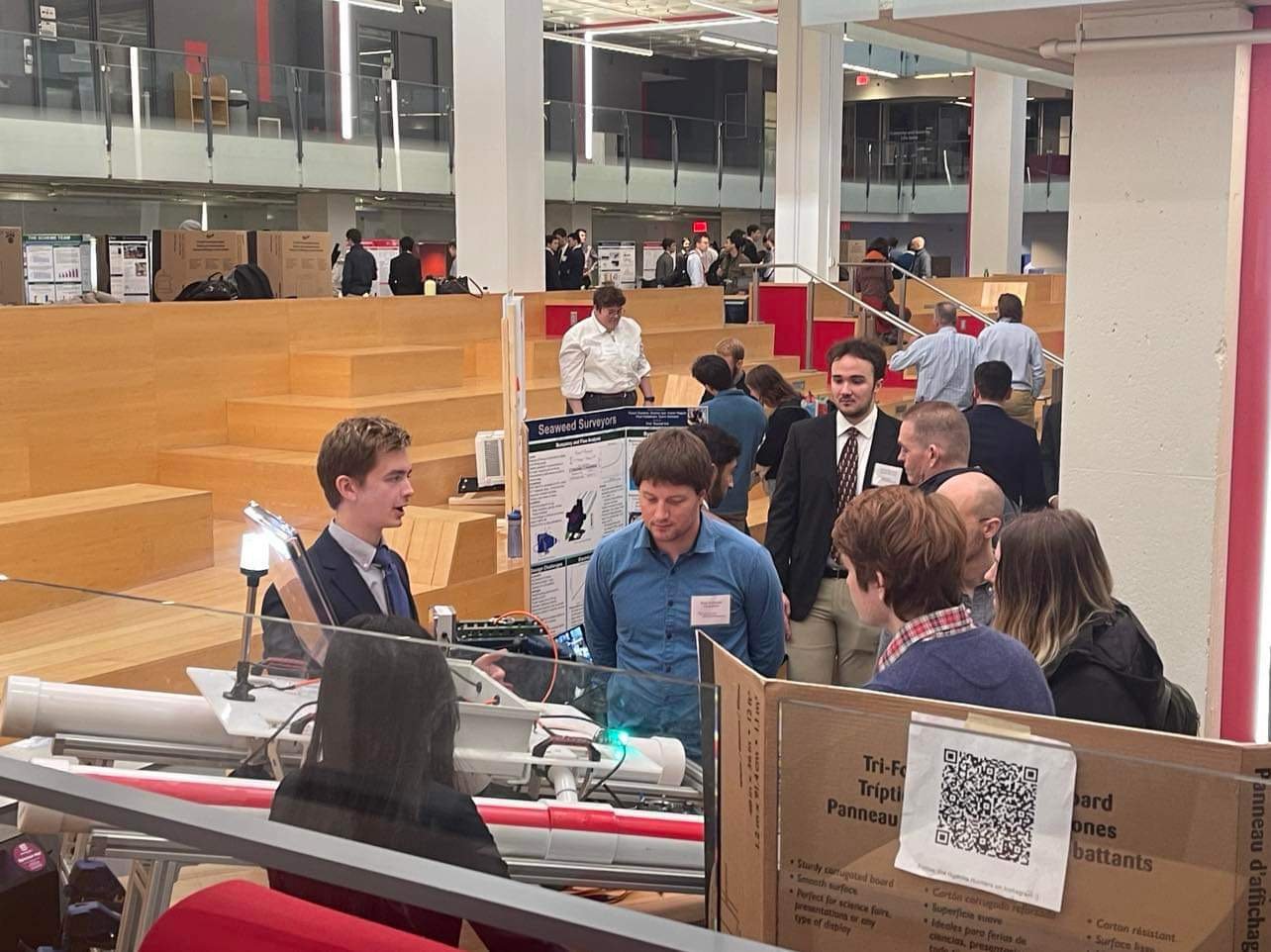
During Capstone Day, we presented our project to a set of judges and defended our design decisions. Afterward, we moved to an open floor at Northeastern’s Curry Student Center to showcase our project and poster to the public. We talked to many people and got to brag about our successes. Then, we moved over to a reception where teams received awards and faculty gave speeches. Our team received the Communications Award for best technical writing.
A month after capstone day, we prepared the boat to transfer to our clients at the Connecticut Agricultural Experiment Station. They’ve given feedback on how usable the boat is to a non-engineer and ideas on how to improve its functionality. Now, the boat belongs to Northeastern’s RIVeR lab, which will take our work and continue it with newer boat versions.