Building a BLDC Motor with a Partial Stator
Please note this project is a work in progress.
For a battle bot project, my friend Noah Ossanna and I are trying to build a robot that spins the majority of its weight using a brushless DC (BLDC) motor architecture. However, we want to save as much weight as possible, so we are using a stator that only has six teeth, inspired by BrokenLinkRobotics. This partial stator makes the motor much less powerful but saves a lot of weight. So, the problem we are facing is an optimization problem: What partial stator motor design will lead to the fastest spin-up time while being as light as possible? Thus far, we’ve learned how BLDC motors function, the equations that drive them, the manufacturing processes, and important design criteria for stators.
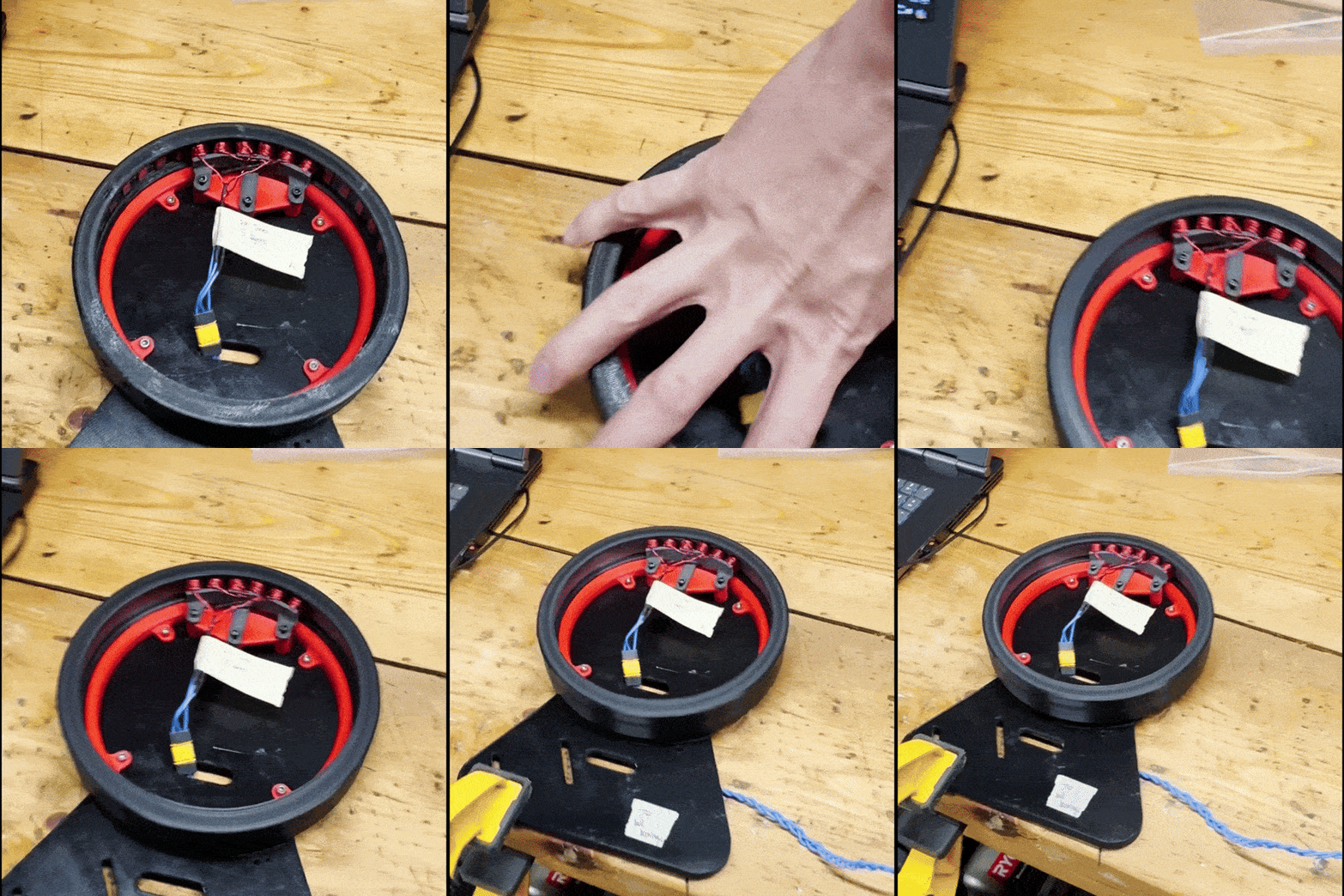
Figure 1 - Video of a 3D printed prototype spinning
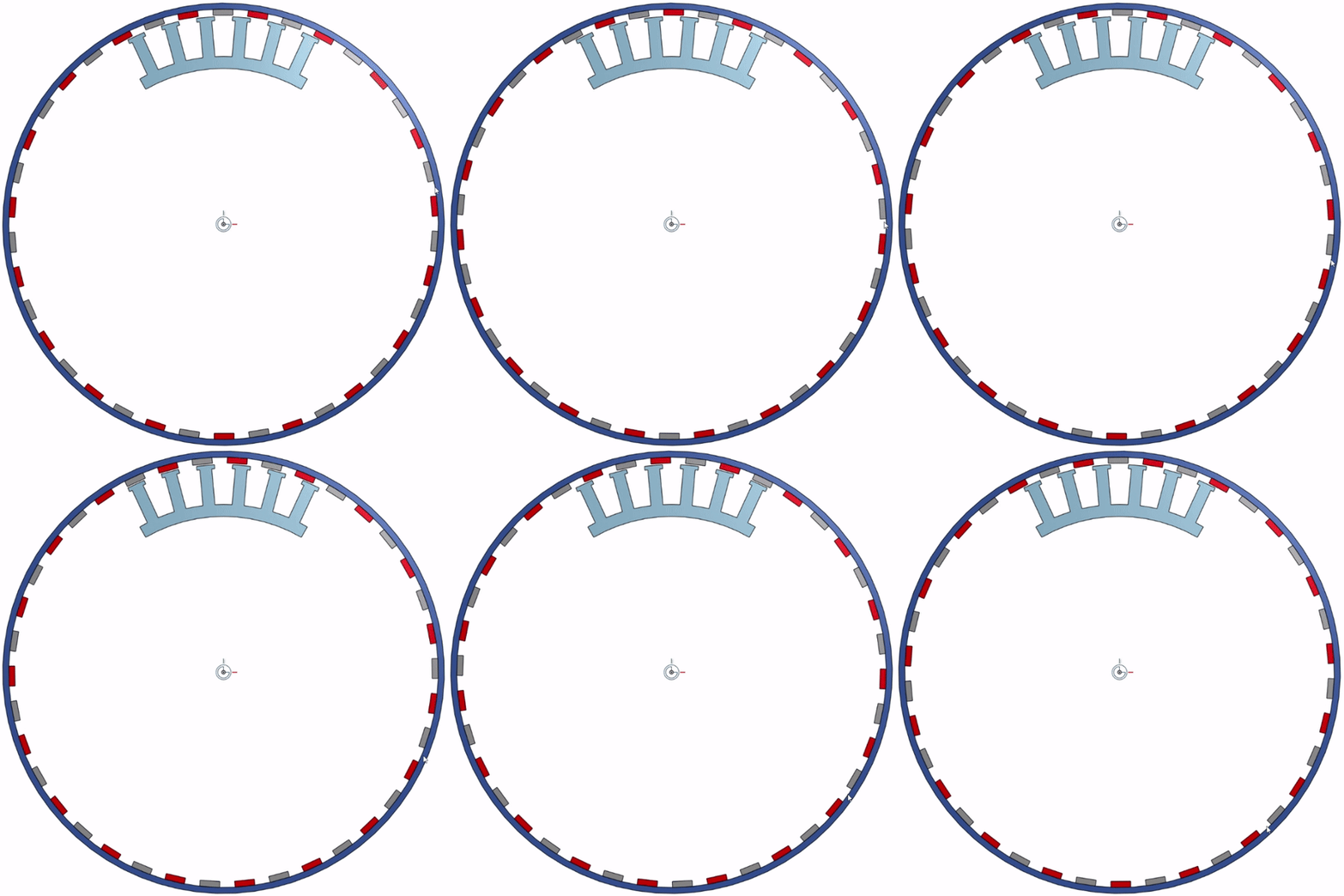
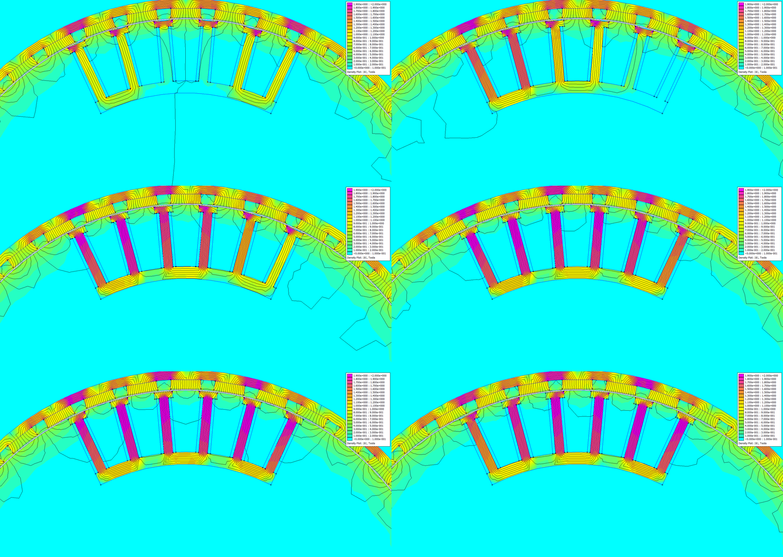
Figure 2 - Animation of a transient simulation attempt
Brushless DC motors are a type of electric motor that sends electricity to copper coils (phases), which are wrapped around pieces of metal (stators) to pull magnets that are placed around a cylinder (rotor). With this architecture, there are many parameters to adjust that could drastically change the performance of the motor. For example, the stator material needs to have a sufficiently high magnetic permeability but a low coercivity, or the coils need to have X minimum number of turns to generate a significant magnetic field, or the airgap between the rotor and the stator needs to be small enough so the stator’s magnetic field can pull the rotor, but large enough to be manufacturable and functional during a battle bot fight. There are many of these kinds of problems to solve when building a motor from scratch, especially one that will experience large forces.
Before building a motor, we wanted to understand what materials and design cues are most important. So, we researched textbooks and forums and found the following:
The winding factor is a key metric for deciding the number of stator teeth (slots) and rotor magnets (poles) to have
The number of slots is a multiple of 3, and number of poles is a multiple of 2
Motor torque is proportional to the winding factor. The higher the winding factor, the better the motor performance
The typical number of layers per coil is 2-3
Ferrous stator materials improve the magnetic strength of the stator
It is best to split the stator into stacks of insulated layers to avoid joule heating from eddy currents from the coil
Halbach arrays could be used inside the rotor to improve stator-rotor interactions
Figure 3 - Basic demonstration of a rotor spinning around a partial stator
Testing Halbach Arrays
For my final project for my Statistics and Stochastic Processes course, I decided to compare the effective distance of a magnetic field for a Halbach array and a non-Halbach array, which both use N52 3mmx6mmx12mm magnets. Over a weekend, I built a test stand that would use a NEMA17 stepper motor with a belt to move a digital hall effect sensor slowly towards an array of magnets. I placed a limit switch in the back to act as a zero point. Whenever the setup made a measurement, it would zero the machine and count the travel distance before the sensor detected a magnetic field. Once the hall sensor was close enough to the array and sent a signal to the microcontroller running the program, the motor would stop, the controller would print the measured distance, and the machine would zero the sensor again for another measurement. I calibrated the distance measurements using a ruler and adjusted the tracked number of steps traveled by the motor.
With this setup, I measured the effective distance of a magnetic array 30 times before changing the number and order of the magnets. This gave me enough data to perform a rudimentary ANOVA analysis and Bonferroni tests, as required by the course. I found that with this set of magnets, Halbach arrays can emit the same magnetic field strength 3mm farther than non-Halbach arrays.
We learned that most stators were made of electric steel - a type of silicone steel that has high permeability and low coercivity. However, we wanted to know if there was a cheaper material that had similar properties. So, I did a survey of different metals using Encyclopedia Magnetica to decide on viable replacements for e-steel. The result is the table below that shows what materials have better permeability and comparable electric resistivity. Despite the search, we realized that the cost of sourcing these materials was comparable to simply purchasing electric steel. With confidence that electric steel is a good option for our stator, we purchased laminated electric steel sheets from AliExpress.
Partial Stator Optimization
Since there are many parameters that affect the performance of a BLDC motor, I needed a way to sweep through different parameters to find an optimal stator geometry. Luckily, Noah found an open-source finite element modeling software for magnetics called FEMM, designed by David Meeker. Meeker also published a Python interface with his simulation software, and I wrote a Python script to set up and run a FEMM simulation given a stator profile in a .DXF file format. Since FEMM does not model motion nor transients, I am trying to create a pseudo-transient simulation to get the change in torque over time by applying the governing differential equation of a BLDC motor:
Screenshot taken from “Electric Motor Control DC, AC, and BLDC Motors” by Sang-Hoon Kim, Kangwon National University
To check whether our design was within a feasible range, I 3D printed the stator and rotor and ran a test. Based on Noah’s decision to use 36 slots and 38 poles, I designed the rotor to hold 38 N52 3x6x12mm magnets. I printed the rotor out of PETG plastic and used JB weld to hold the magnets. I then 3D printed the stator using PLA with embedded iron shards, also known as magnetic PLA. This would help amplify the magnetic strength within each stator coil. I then wound 22 AWG magnet wire in a Wye configuration and soldered an MR30 connector to the three phases. I then used Noah’s code to program an ESP32 to send speed signals to a BLHeli32 ESC. I also used a 6S LiPo battery to power the motor. I also attached a Hall effect sensor to the base of the test stand to read when the poles switch, allowing me to calculate a rotor speed. At the moment, I am working on how to parse through the data to get reliable speed measurements. Unfortunately, the sample rate for the hall sensor is too low to easily see the speed, so I will have to redesign the rotor to make detection easier. Below is a video of the motor successfully spinning.


